Vacuum hose diagrams, May 2002
These were based on the existing hose locations on my truck, and do not show the California and High Altitude variants.
This diagram (2 of 4) intends to show how the Thermo Valve is interconnected.
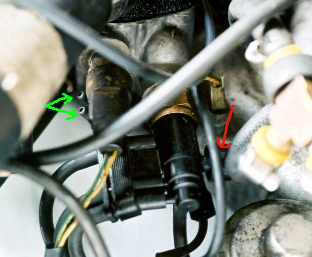
The Thermo Valve is easily recognised by the round vent (red arrow)on its right side. The Thermo switch ports (see diagram #1, it's not part of the Thermovalve) are indicated with the green arrows.
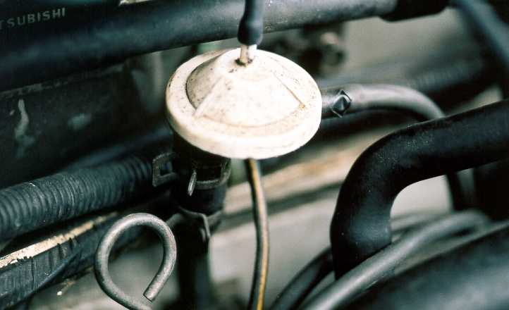
The Purge Control Valve is behind the engine, on the firewall. Mine has a worn spot on the hose...
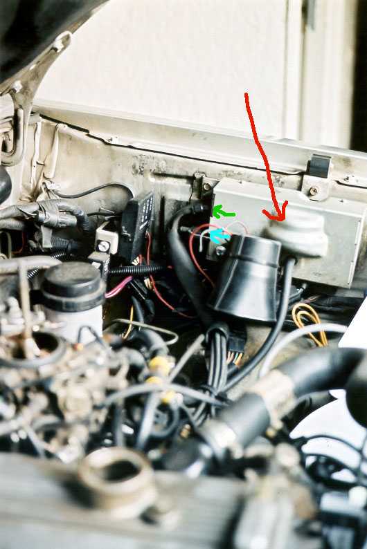
The device box (red arrow) sits on the fender wall on the driver's side of the engine compartment. There are 2 rows of hose connectors: upper (green arrow), and lower (blue arrow).
Diagram 1
Diagram 3
Diagram 4
back to main page